|
|


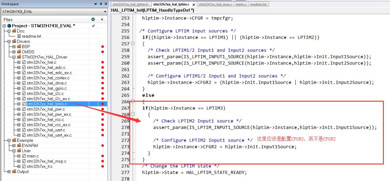
感谢坛友指出,HAL库这么操作是没有问题的。
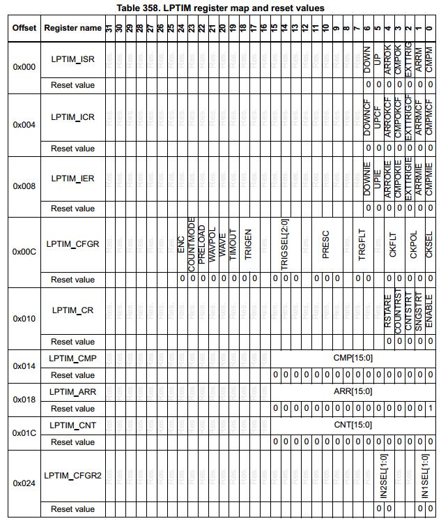
根据寄存器map文件,LPTIM_CFGR2和LPTIM3_CFGR2是在同一个偏移地址。


而LPTIM1 - LPTIM5这五个外设的寄存器的地址不同,实际操作起来并不会有问题,HAL库这里的处理,如果不看参考手册,容易想当然,以为LPTIM_CFGR2和LPTIM3_CFGR2是不同的偏移地址
#define PERIPH_BASE ((uint32_t)0x40000000)
#define D2_APB2PERIPH_BASE (PERIPH_BASE + 0x00010000)
#define D3_APB1PERIPH_BASE (PERIPH_BASE + 0x18000000)
#define LPTIM1_BASE (D2_APB1PERIPH_BASE + 0x2400)
#define LPTIM2_BASE (D3_APB1PERIPH_BASE + 0x2400)
#define LPTIM3_BASE (D3_APB1PERIPH_BASE + 0x2800)
#define LPTIM4_BASE (D3_APB1PERIPH_BASE + 0x2C00)
#define LPTIM5_BASE (D3_APB1PERIPH_BASE + 0x3000)
#define LPTIM1 ((LPTIM_TypeDef *) LPTIM1_BASE) <----- 展开这个宏,(TIM_TypeDef *) 0x40012400
#define LPTIM2 ((LPTIM_TypeDef *) LPTIM2_BASE)
#define LPTIM3 ((LPTIM_TypeDef *) LPTIM3_BASE) <----- 展开这个宏,(TIM_TypeDef *) 0x58002800
#define LPTIM4 ((LPTIM_TypeDef *) LPTIM4_BASE)
#define LPTIM5 ((LPTIM_TypeDef *) LPTIM5_BASE)
然后HAL库的寄存器定义里面也比较省事,直接仅定义了CFGR2。
typedef struct
{
__IO uint32_t ISR; /*!< LPTIM Interrupt and Status register, Address offset: 0x00 */
__IO uint32_t ICR; /*!< LPTIM Interrupt Clear register, Address offset: 0x04 */
__IO uint32_t IER; /*!< LPTIM Interrupt Enable register, Address offset: 0x08 */
__IO uint32_t CFGR; /*!< LPTIM Configuration register, Address offset: 0x0C */
__IO uint32_t CR; /*!< LPTIM Control register, Address offset: 0x10 */
__IO uint32_t CMP; /*!< LPTIM Compare register, Address offset: 0x14 */
__IO uint32_t ARR; /*!< LPTIM Autoreload register, Address offset: 0x18 */
__IO uint32_t CNT; /*!< LPTIM Counter register, Address offset: 0x1C */
uint16_t RESERVED1; /*!< Reserved, 0x20 */
__IO uint32_t CFGR2; /*!< LPTIM Option register, Address offset: 0x24 */
} LPTIM_TypeDef;
然后下面的操作已经将地址区分开。
LPTIM1 ->CFGR2 对应地址 0x40012400 + 0x24
LPTIM3 ->CFGR2 对应地址 0x58002800 + 0x24
|
|


 发表于 2019-1-3 02:00:19


 发表于 2019-1-3 08:55:52


 楼主
楼主
