|
|
说明:
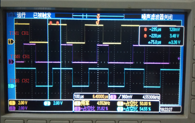
官方配套的例子实现了一个TIM1的CH1作为触发,主控模式;TIM8作为从控模式。
他这模式有一点不太理解,相移后,占空比的计算,发现怎么算都不太对。
输出效果如下:


- /* Private typedef -----------------------------------------------------------*/
- /* Private define ------------------------------------------------------------*/
- #define INITIAL_PHASE (uint32_t) 15000
- #define INITIAL_LENGTH (uint32_t) 5000
- #define PWM_FREQUENCY (uint32_t) 22000
- /* Private macro -------------------------------------------------------------*/
- /* Private variables ---------------------------------------------------------*/
- /* Timer handler declaration */
- TIM_HandleTypeDef TimHandle8;
- TIM_HandleTypeDef TimHandle1;
- /* Timer Output Compare Configuration Structure declaration */
- TIM_OC_InitTypeDef sConfig;
- /* Master and slave configurations */
- TIM_SlaveConfigTypeDef sSlaveConfig;
- TIM_MasterConfigTypeDef sMasterConfig;
- /* Private function prototypes -----------------------------------------------*/
- static void SystemClock_Config(void);
- static void Error_Handler(void);
- static void CPU_CACHE_Enable(void);
- /* Private functions ---------------------------------------------------------*/
- /**
- * @brief Main program
- * @param None
- * @retval None
- */
- int main(void)
- {
- /* Enable the CPU Cache */
- CPU_CACHE_Enable();
-
- /* STM32H7xx HAL library initialization:
- - Systick timer is configured by default as source of time base, but user
- can eventually implement his proper time base source (a general purpose
- timer for example or other time source), keeping in mind that Time base
- duration should be kept 1ms since PPP_TIMEOUT_VALUEs are defined and
- handled in milliseconds basis.
- - Set NVIC Group Priority to 4
- - Low Level Initialization
- */
- HAL_Init();
- /* Configure the system clock to 400 MHz */
- SystemClock_Config();
- /*##-1- Configure the TIM peripheral #######################################*/
- /* ---------------------------------------------------------------------------
- TIM8 is configured to generate an Asymetric signal with a programmable
- Phase-Shifted signal on TIM8_CH2:
- - TIM8 Channel 1 is configured in PWM2 mode
- - TIM8 Channel 2 is configured in Asymetric PWM2 mode
- - The counter mode is center aligned mode
- - The pulse length and the phase shift are programmed consecutively in TIM8_CCR2 and TIM8_CCR1.
-
- TIM1 is configured to generating the reference signal on Channel1 used by TIM8:
- - TIM1 is generating a PWM signal with frequency equal to 4.54 KHz
- - TIM1 is used as master for TIM8, the update event of TIM1 genarates the Reset counter
- of TIM8 to synchronize the two signals: the reference signal (TIM1_CH1) and
- the shifted signal (TIM8_CH2).
-
- In this example TIM1 and TIM8 input clock (TIM18CLK) is set to APB2 clock (2*PCLK2)
- TIM1 and TIM8 signals are at frequency of ((SystemCoreClock/2) / (PWM_FREQUENCY + 1))
-
- TIM8 is gerating a signal with the following caracteristics:
- - Pulse lenght = (TIM8_CCR1 + TIM8_CCR2) / TIM8_CLK
- - Phase shift = TIM8_CCR1/TIM8_CLK
- with TIM8_CLK = ((SystemCoreClock/2) / (Period + 1)), as the prescaler is equal to zero.
-
- Note:
- SystemCoreClock variable holds HCLK frequency and is defined in system_stm32h7xx.c file.
- Each time the core clock (HCLK) changes, user had to update SystemCoreClock
- variable value. Otherwise, any configuration based on this variable will be incorrect.
- This variable is updated in three ways:
- 1) by calling CMSIS function SystemCoreClockUpdate()
- 2) by calling HAL API function HAL_RCC_GetSysClockFreq()
- 3) each time HAL_RCC_ClockConfig() is called to configure the system clock frequency
- --------------------------------------------------------------------------- */
- /* Initialize Timers: TIM1 & TIM8 */
- TimHandle1.Instance = TIM1;
- TimHandle1.Init.Prescaler = 0;
- TimHandle1.Init.Period = 2 * PWM_FREQUENCY;
- TimHandle1.Init.ClockDivision = 0;
- TimHandle1.Init.CounterMode = TIM_COUNTERMODE_UP;
- TimHandle1.Init.RepetitionCounter = 0;
- if(HAL_TIM_PWM_Init(&TimHandle1) != HAL_OK)
- {
- /* Initialization Error */
- Error_Handler();
- }
- TimHandle8.Instance = TIM8;
- TimHandle8.Init.Prescaler = 0;
- TimHandle8.Init.Period = PWM_FREQUENCY;
- TimHandle8.Init.ClockDivision = 0;
- TimHandle8.Init.CounterMode = TIM_COUNTERMODE_CENTERALIGNED1;
- TimHandle8.Init.RepetitionCounter = 0;
- if(HAL_TIM_PWM_Init(&TimHandle8) != HAL_OK)
- {
- /* Initialization Error */
- Error_Handler();
- }
- /*##-2- Configure the PWM channels #########################################*/
- /* Channels 1&2 configuration on TIM8 */
- sConfig.OCMode = TIM_OCMODE_PWM2;
- sConfig.Pulse = INITIAL_PHASE;
- sConfig.OCPolarity = TIM_OCPOLARITY_HIGH;
- sConfig.OCNPolarity = TIM_OCNPOLARITY_HIGH;
- sConfig.OCFastMode = TIM_OCFAST_DISABLE;
- sConfig.OCIdleState = TIM_OCIDLESTATE_RESET;
- sConfig.OCNIdleState = TIM_OCNIDLESTATE_RESET;
- if(HAL_TIM_PWM_ConfigChannel(&TimHandle8, &sConfig, TIM_CHANNEL_1) != HAL_OK)
- {
- /* Configuration Error */
- Error_Handler();
- }
- sConfig.OCMode = TIM_OCMODE_ASSYMETRIC_PWM2;
- sConfig.Pulse = INITIAL_LENGTH;
- if(HAL_TIM_PWM_ConfigChannel(&TimHandle8, &sConfig, TIM_CHANNEL_2) != HAL_OK)
- {
- /* Configuration Error */
- Error_Handler();
- }
-
- /* Channel1 configuration on TIM1 */
- sConfig.OCMode = TIM_OCMODE_PWM1;
- sConfig.Pulse = PWM_FREQUENCY;
- if(HAL_TIM_PWM_ConfigChannel(&TimHandle1, &sConfig, TIM_CHANNEL_1) != HAL_OK)
- {
- /* Configuration Error */
- Error_Handler();
- }
- /*##-3- Configure master/slave mode and trigger ############################*/
- /* Synchronization between TIM1 and TIM8
- The aim is to generate a reference signal on TIM1_CH1
- The Phase-Shifted signal generated on TIM8_CH2 is compared to the reference
- signal */
- /* Configure TIM8 in slave mode: an active edge on trigger input generates a
- reset on TIM8 */
- sSlaveConfig.SlaveMode = TIM_SLAVEMODE_RESET;
- sSlaveConfig.InputTrigger = TIM_TS_ITR0;
- sSlaveConfig.TriggerPolarity = TIM_TRIGGERPOLARITY_NONINVERTED;
- sSlaveConfig.TriggerPrescaler = TIM_TRIGGERPRESCALER_DIV1;
- sSlaveConfig.TriggerFilter = 0;
- if(HAL_TIM_SlaveConfigSynchronization(&TimHandle8, &sSlaveConfig) != HAL_OK)
- {
- /* Configuration Error */
- Error_Handler();
- }
- /* Configure TIM1 in master mode */
- sMasterConfig.MasterOutputTrigger = TIM_TRGO_UPDATE;
- sMasterConfig.MasterOutputTrigger2 = TIM_TRGO2_RESET;
- sMasterConfig.MasterSlaveMode = TIM_MASTERSLAVEMODE_DISABLE;
- if(HAL_TIMEx_MasterConfigSynchronization(&TimHandle1, &sMasterConfig) != HAL_OK)
- {
- /* Configuration Error */
- Error_Handler();
- }
-
- /*##-4- Start PWM signals generation #######################################*/
- /* Start TIM1 channel 1 */
- if(HAL_TIM_PWM_Start(&TimHandle1, TIM_CHANNEL_1) != HAL_OK)
- {
- /* PWM Generation Error */
- Error_Handler();
- }
- /* Start TIM8 channel 1 */
- if(HAL_TIM_PWM_Start(&TimHandle8, TIM_CHANNEL_1) != HAL_OK)
- {
- /* PWM Generation Error */
- Error_Handler();
- }
- /* Start TIM8 channel 2 */
- if(HAL_TIM_PWM_Start(&TimHandle8, TIM_CHANNEL_2) != HAL_OK)
- {
- /* PWM Generation Error */
- Error_Handler();
- }
- while (1)
- {
- }
- }
|
|


 发表于 2018-8-23 00:56:44


 发表于 2021-7-8 10:50:38
 楼主
楼主