|
|
说明:
实现方法就是通过DMA更新捕获比较寄存器CCR,从而实现不同的占空比效果。
此时再配合定时器的重复计数器RCR,可以设置多少个更新周期后切换一次CCR捕获比较寄存器的数值。
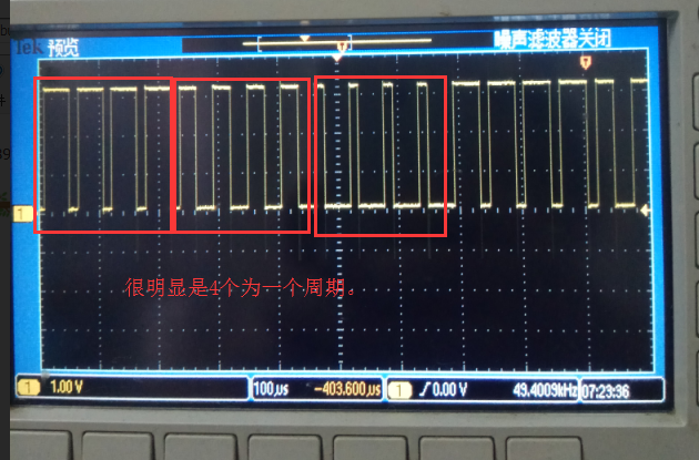
实际调试发现也使能预装载了,即产生更新事件后才实际更新CCR的数值,但是设置的RCR值没有起到任何作用。
原因分析:
已经解决,是官方例子bug,看此贴就明白了:http://www.armbbs.cn/forum.php?mod=viewthread&tid=88977
效果:

正常效果应该是下面这个:
程序:
- /**
- * @brief Main program.
- * @param None
- * @retval None
- */
- int main(void)
- {
-
- /* Enable the CPU Cache */
- CPU_CACHE_Enable();
- /* This sample code shows how to use DMA with TIM3 Update request to transfer
- Data from memory to TIM3 Capture Compare Register 3 (CCR3), through the
- STM32H7xx HAL API. To proceed, 3 steps are required */
- /* STM32H7xx HAL library initialization:
- - Systick timer is configured by default as source of time base, but user
- can eventually implement his proper time base source (a general purpose
- timer for example or other time source), keeping in mind that Time base
- duration should be kept 1ms since PPP_TIMEOUT_VALUEs are defined and
- handled in milliseconds basis.
- - Set NVIC Group Priority to 4
- - Low Level Initialization
- */
- HAL_Init();
- /* Configure the system clock to 400 MHz */
- SystemClock_Config();
- /* Configure LED2 */
- BSP_LED_Init(LED2);
- /* Compute the value of ARR regiter to generate signal frequency at 17.57 Khz */
- uwTimerPeriod = (uint32_t)(((SystemCoreClock/2) / 17570) - 1);
- /* Compute CCR1 value to generate a duty cycle at 75% */
- aCCValue_Buffer[0] = (uint32_t)(((uint32_t) 75 * (uwTimerPeriod - 1)) / 100);
- /* Compute CCR2 value to generate a duty cycle at 50% */
- aCCValue_Buffer[1] = (uint32_t)(((uint32_t) 50 * (uwTimerPeriod - 1)) / 100);
- /* Compute CCR3 value to generate a duty cycle at 25% */
- aCCValue_Buffer[2] = (uint32_t)(((uint32_t) 25 * (uwTimerPeriod - 1)) / 100);
- /* Clean Data Cache to update the content of the SRAM to be used by the DMA */
- SCB_CleanDCache_by_Addr((uint32_t *) aCCValue_Buffer, sizeof(aCCValue_Buffer) );
-
- /*##-1- Configure the TIM peripheral #######################################*/
- /* ---------------------------------------------------------------------------
- TIM3 input clock (TIM3CLK) is set to APB1 clock (PCLK1)x2, since APB1
- prescaler is 4.
- TIM3CLK = PCLK1*2
- PCLK1 = HCLK/2
- => TIM3CLK = HCLK/2 = SystemCoreClock/2
- TIM3CLK = (SystemCoreClock/2), Prescaler = 0, TIM3 counter clock = (SystemCoreClock/2)
- SystemCoreClock is set to 400 MHz for STM32H7xx devices.
- The objective is to configure TIM3 channel 3 to generate a PWM
- signal with a frequency equal to 17.57 KHz:
- - TIM3_Period = ((SystemCoreClock/2) / 17570) - 1
- and a variable duty cycle that is changed by the DMA after a specific number of
- Update DMA request.
- The number of this repetitive requests is defined by the TIM3 Repetition counter,
- each 4 Update Requests, the TIM3 Channel 3 Duty Cycle changes to the next new
- value defined by the aCCValue_Buffer.
- Note:
- SystemCoreClock variable holds HCLK frequency and is defined in system_stm32h7xx.c file.
- Each time the core clock (HCLK) changes, user had to update SystemCoreClock
- variable value. Otherwise, any configuration based on this variable will be incorrect.
- This variable is updated in three ways:
- 1) by calling CMSIS function SystemCoreClockUpdate()
- 2) by calling HAL API function HAL_RCC_GetSysClockFreq()
- 3) each time HAL_RCC_ClockConfig() is called to configure the system clock frequency
- -----------------------------------------------------------------------------*/
- /* Initialize TIM3 peripheral as follows:
- + Period = TimerPeriod (To have an output frequency equal to 17.570 KHz)
- + Repetition Counter = 3
- + Prescaler = 0
- + ClockDivision = 0
- + Counter direction = Up
- */
- TimHandle.Instance = TIMx;
- TimHandle.Init.Period = uwTimerPeriod;
- TimHandle.Init.RepetitionCounter = 1;
- TimHandle.Init.Prescaler = 0;
- TimHandle.Init.ClockDivision = 0;
- TimHandle.Init.CounterMode = TIM_COUNTERMODE_UP;
- if (HAL_TIM_PWM_Init(&TimHandle) != HAL_OK)
- {
- /* Initialization Error */
- Error_Handler();
- }
- /*##-2- Configure the PWM channel 3 ########################################*/
- sConfig.OCMode = TIM_OCMODE_PWM1;
- sConfig.OCPolarity = TIM_OCPOLARITY_HIGH;
- sConfig.Pulse = aCCValue_Buffer[0];
- sConfig.OCNPolarity = TIM_OCNPOLARITY_HIGH;
- sConfig.OCFastMode = TIM_OCFAST_DISABLE;
- sConfig.OCIdleState = TIM_OCIDLESTATE_RESET;
- sConfig.OCNIdleState = TIM_OCNIDLESTATE_RESET;
- if (HAL_TIM_PWM_ConfigChannel(&TimHandle, &sConfig, TIM_CHANNEL_3) != HAL_OK)
- {
- /* Configuration Error */
- Error_Handler();
- }
- /*##-3- Start PWM signal generation in DMA mode ############################*/
- if (HAL_TIM_PWM_Start_DMA(&TimHandle, TIM_CHANNEL_3, aCCValue_Buffer, 3) != HAL_OK)
- {
- /* Starting Error */
- Error_Handler();
- }
- while (1)
- {
- }
- }
|
|


 发表于 2018-8-14 13:29:44
 发表于 2018-8-14 13:35:01
 楼主
楼主
